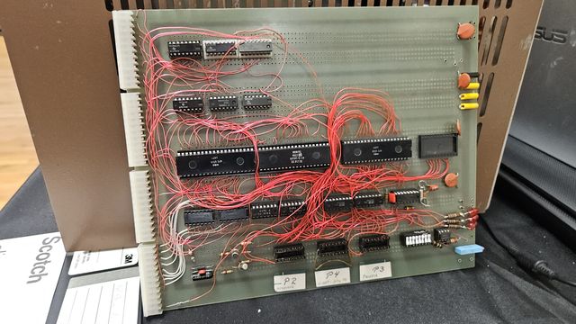
This is an example of a do it yourself board using the OSI 495 prototype board. On the backside there are rows of 3 pads connected together. One gets an IC lead and the other two get wires soldered to them for connecting the chips. With two pads you can daisy chain the signal with one bringing the signal in and the other sending it to the next chip.
I didn't get any documentation with it. Labels on the DIP sockets on the bottom used as connectors are keyboard, U-ART-RTTY TU, and printer. RTTY TU is Radio Teletype Terminal Unit which converts between digital data and audio tones encoding the data for RF transmission. This allowed the computer to send and receive radio teletype data. The computer may have been just emulating a Teletype using the keyboard and printer.
Back to Previous page All of VCF East 2026 pictures
Feel free to contact me, David Gesswein djg@pdp8online.com with any questions, comments on the web site, or if you have related equipment, documentation, software etc. you are willing to part with. I am interested in anything PDP-8 related, computers, peripherals used with them, DEC or third party, or documentation.
PDP-8 Home Page PDP-8 Site Map PDP-8 Site Search